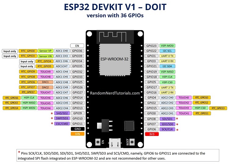
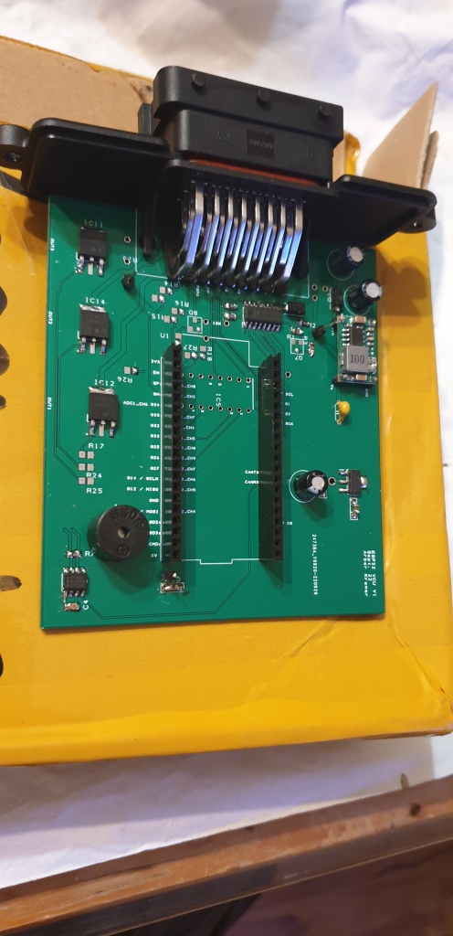
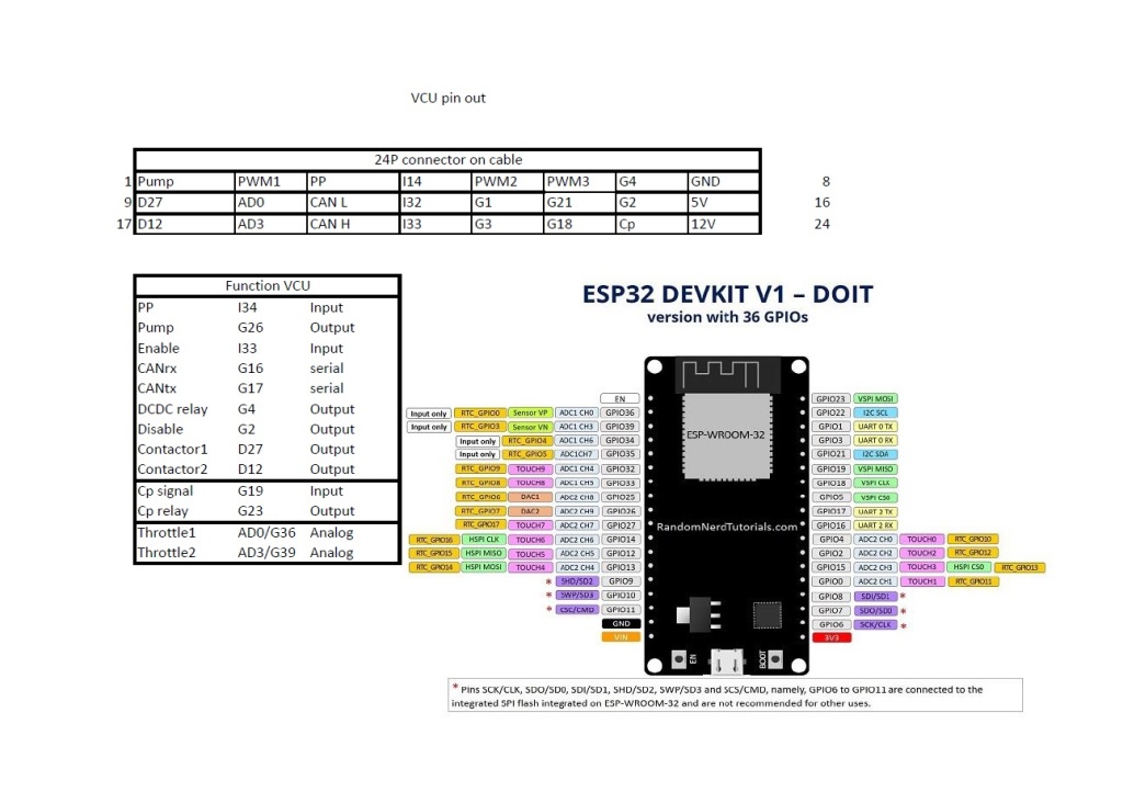
I have prepared a board with ESP32 chip for testing and VCU development.
Main caveat is this only has a single CAN. While i develop the code i intend to add another CAN to SPI pins… this should make it a great board especially so since it has BT/WiFi functionality already integrated.
I managed to get the CAN bus code working YAY! I have the I/Os working as well, though not in the way as i intended. I will simply replace that chip by series of 4 resistors and reverse the sensing. This will pull the signal lines to GND and effect signal change in ESP32 chip. Buzzer coupled with signal on BMS pin is really loud. I had to tape it over for testing.
This board for now drives only one CAN transciever. I consider it enough for now. Later i will add another SPI if need be, but i see quite a lot of development to do that. For now the code itself is enough of a challenge
I have already implemented PP and CP signalling. Board also has PWM duty sensing pin which can be used to correct power as required from the EVSE.
This version of VCU actually could also be used to run Leaf or Outlander inverter. It has the analog pins and correct inputs and outputs as well. I tested those analog inputs and they are a bit off as the digital signal value looks. It seems integrated analog inputs are not very accurate despite the high bit rate. I will probably have to use external AD chip on I2C lines.
I tested ESP32 12V signal however sensing on one of my analog inputs. Rather cubersome, using throttle input for that but it works. And i can use this signal to observe aux voltage and turn on DCDC if aux voltage goes down.
On the more important note i managed to setup watchdog function so it does not reset the chip every so often… CAN bus signaling works within function now.
I used flags as conditionals do not work with yet undeclared parameters (can values). VCU would read Mitsubishi charger/DCDC aux voltage from CAN and decide to start it up if it drops too low. On the charge side VCU would read HV voltage and stop charger from going too high. There are AC compressor and heater functions too. Tesla DCDC CAN signal and Eltek charger commands i tested too.
To be more precise; i published the VCU code which works with Mitsubishi, Eltek, Elcon and Tesla CAN commands. It can sense EVSE presence and react with running coolant pump and DCDC. Aux battery monitoring function is added to keep 12V system topped up. I set it up to use flag state within CAN functions. That way one can use single event for multiple functions in real time.
For now i use it with external relays since most of the outputs are open collector based.
Next on the list is the Wifi function. The idea is to use ESP32 wifi output to send serial data out and report on the several parameters the VCU can gather from CAN bus.
Because of shortage of chips i couldnt play with Teensy or DUE anymore. However I noticed increasing popularity of ESP32 family of chips.
ESP32 is a low-cost, low-power system on a chip microcontrollers with integrated Wi-Fi and dual-mode Bluetooth. It has Tensilica Xtensa LX6 microprocessor with two cores. I barely schratched the surface with one core control, but while reading about it it seems it has really robust watchdog process which makes it a good candidate for VCU chip.
I am not so sure about ADC pins. I read about them not being really accurate but rather adequate.
It only has a single CAN controler. It will be ok for testing. Later on for BMS and VCU functionality it could be sufficient. However to use full integration i may build a dual CAN bus version with second controler on SPI.
Also SPI consumes a lot of pins therefore i would need to use a digital port expander such as MCP23S17. But i will get to this later if i need it at all.
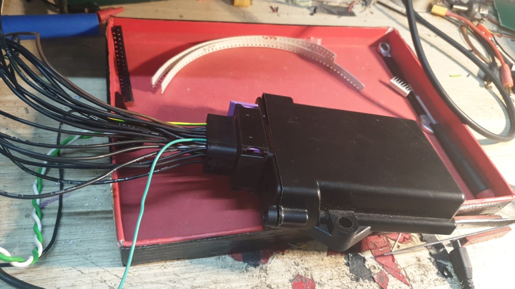
It is simple enough casing sealed against weather and robust enough to fit in the trunk or under the hood.
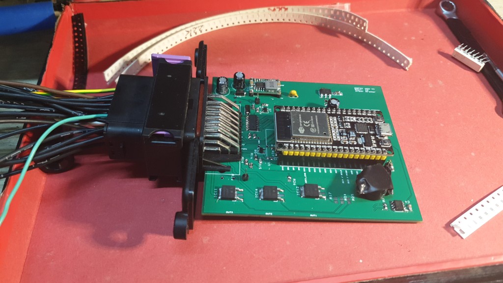
I designed it to be fed from 12V supply. Integrated is a 5V regulator with additional 3V3 LDO regulator to provide stable logic voltage for ESP32. 5V is there simply because it is easier to transition from 12V to 5V and then to 3V3 than directly to 3V3. Also there is 5V layer onboard which can be used as supply for throttle or other analog sensors.
Onboard there are 3 powerfull switches NCV8401A which can clamp heavy relays or 12V moderate loads directly.
4x opto coupled input circuit.
ULN2003 darlington array for signaling or triggering low loads and driving PWM.
I have a set of 6 Hankzor active balancers that are not quite BMS, but they gather data, balance and can output data on CAN bus. What is revolutionary for me is that those balancers can ACTIVELY balance cells. This means capacitively adding charge to the lowest cell whilst taking from higher charged cells in a pack.
Communication works at 250kbps at 11bit ID. Each unit needs to have its own ID which is set by the DIP switches on the side of the module. Here is the translation table for different switch positions.
DIP Position / Fixed address no.
1
2
3
4
0
OFF
OFF
OFF
OFF
1
ON
OFF
OFF
OFF
2
OFF
ON
OFF
OFF
3
ON
ON
OFF
OFF
4
OFF
OFF
ON
OFF
5
ON
OFF
ON
OFF
6
OFF
ON
ON
OFF
7
ON
ON
ON
OFF
8
OFF
OFF
OFF
ON
I mounted each 16S module with its own balancer module. Iach comes with one thermistor and CAN bus line. Also i could set addressing on the sides of the modules. I decided i began with no. 1 module at the first +HV connection. The last module is no. 6 at the rear with -HV connection.
CAN bus is dormant until master requests data from particular module. When that is accomplished that module dumps several lines of data on the CAN bus. ID is still the same for every line, but data is classified by the first byte of the line. For example 01 in byte1 is reserved for cell temperature values and 04 is actual cell values…
Master request: ID 01 DATA FF
Slave response: ID 01 DATA 01 00 11 24 F9 0F 68 18 ID 01 DATA 02 10 03 02 00 2C 04 5A ID 01 DATA 03 00 05 03 E8 01 18 ID 01 DATA 04 00 0F 64 0F 61 0F 61 ID 01 DATA 04 03 0F 60 0F 60 0F 67 ID 01 DATA 04 06 0F 61 0F 61 0F 62 ID 01 DATA 04 09 0F 73 0F 6B 0F 61 ID 01 DATA 04 0C 0F 69 0F 73 0F 71 ID 01 DATA 04 0F 0F 6B 0F 8C 0F 64 ID 01 DATA 04 12 0F 65 0F 62 0F 65 ID 01 DATA 04 15 0F 65 0F 6F 0F 60
ID: 01 cell voltage report explained
Response data: 01 00 15 1E D3 0F 69 14;
Temperature 0x0015 * 1 ℃ = 21 ℃
Total voltage 0x1ED3 * 10mV = 7891 * 10mV = 78.910V
Number of identification units: 0x14 in HEX = 20 cells
I could use this particular report to determin number of places in array!
Response data: 04 00 0F 69 0F 69 0F 67;
Starting measure No 0x00 = 0 means beginning of array!
measure 0 Voltage 0xoF69 * 1mV = 3945mV = 3.945V
measure 1 voltage 0x0F69 * 1mV = 3945mV = 3.945V
measure 2 voltage 0x0F67 * 1mV = 3943mV = 3.943V
Response data: 04 03 0F 69 0F 68 0F 67;
Starting voltage No 0x03 = 0
measure 3 Voltage 0x0F69 * 1mV = 3945mV = 3.945V
measure 4 voltage 0x0F68 * 1mV = 3944mV = 3.944V
measure 5 voltage 0x0F67 * 1mV = 3943mV = 3.943V
Response data: 04 06 0F 68 0F 68 0F 6C;
Starting voltage No 0x06 = 0
measure 6 Voltage 0x0F68 * 1mV = 3944mV = 3.944V
measure 7 voltage 0x0F68 * 1mV = 3944mV = 3.944V
measure 8 voltage 0x0F6C * 1mV = 3948mV = 3.948V
I have built the code to run master command at 500ms intervals thus supplying VCU with stream of cell data.
void sendBMSquerry_1 () // send CAN frame for BMS command
{
 CAN_FRAME txFrame;
    txFrame.rtr = 0;
    txFrame.id = 0x01; // Rotate ID for each report
    txFrame.extended = false;
    txFrame.length = 1; // Data payload 1 byte
    txFrame.data.uint8[0] = 0xFF;
    CAN0.sendFrame(txFrame);
}
Commands need to be send from 1st module to the last, so i made the function revolve.
void requestDATA ()
{
      frameRotate++;
      frameRotate %= 5; // 5 cases
      switch (frameRotate)
      {
        case 0:
          sendBMSquerry_1 ();
          break;
        case 1:
          sendBMSquerry_2 ();
          break;
        case 2:
          sendBMSquerry_3 ();
          break;
        case 3:
          sendBMSquerry_4 ();
          break;
        case 4:
          sendBMSquerry_5 ();
          break;
      }
}
Likewise i setup a command to run balancing when conditions were right
void SendBMSbalancingON_1 () // Turn ON/OFF balancing when cells are within 3.9V
{
 CAN_FRAME txFrame;
    txFrame.rtr = 0;
    txFrame.id = 0x01; // Rotating frame max no. of modules
    txFrame.extended = false;
    txFrame.length = 2; // Data payload 2 bytes
    txFrame.data.uint8[0] = 0xF6;
    txFrame.data.uint8[1] = 0x01; // Use BMS balancing flag to switch on/off
    CAN0.sendFrame(txFrame);
}
And i setup a command to turm off balancing
void SendBMSbalancingOFF_1() // Turn ON/OFF balancing when cells are within 3.9V
{
 CAN_FRAME txFrame;
    txFrame.rtr = 0;
    txFrame.id = 0x01; // Rotating frame max no. of modules
    txFrame.extended = false;
    txFrame.length = 2; // Data payload 2 bytes
    txFrame.data.uint8[0] = 0xF6;
    txFrame.data.uint8[1] = 0x00; // Use BMS balancing flag to switch on/off
    CAN0.sendFrame(txFrame);
}
I decided to make the BMS turn ON balancing only when charger is connected. At the time cells are at rest and balancing can be done efficiently.
Also i made BMS turn OFF balancing when car is driving. Reasoning is cell voltage swing while driving is too great to allow for efficient balancing.
if(digitalRead(PP_pin) == LOW) { // if PP_pin senses EVSE
  if(millis()-last > transmitime)  //Nominally set for 100ms - do stuff on 100 ms non-interrupt clock
    {
     last=millis();        //Zero our timer
       requestBMS_ON ();
Serial.println("Put BMS in charge mode");
    } }

if(digitalRead(Enable_pin) == HIGH) { // if PP_pin senses EVSE
  if(millis()-last > transmitime)  //Nominally set for 100ms - do stuff on 100 ms non-interrupt clock
    {
     last=millis();        //Zero our timer
       requestBMS_OFF ();
Serial.println("Put BMS in drive mode");
 }}
Additionaly i will add several alarm states such as:
cell Over Temperature Alarm…..OOOOOL
cell Under Temperature Alarm…OOOOOOL
cell Over Voltage Alarm………….OOOL
cell Under Voltage Alarm………..OOL
cell Voltage Difference Alarm….OOOOL
BMS change of balancing state…OL
Alarm beep consists of short beeps and a single long beep to signify classification of alarm. For example a single short beep and long beep will mean VCU veaking up from reset.
I will program alarms by severity and similarity
Some alarms would only warn user by a series of beeps. Others would activate BMS output pin which will disable charging or driving.
Each alarm state will require change of state to be reset. Either transition from charging to driving or from drive to charge…
I designed this board because someone asked me to develop two independant controls for two motors.
I remembered in the past when i designed similar board for 2x Openinverter brains. It was rather complex and all controls were duplicated.
Well here i decided to keep it simple.
Lebowski inverter uses dsPic30f4011 chip which was purposely made to control 3 phase motors.
There is a single input from 12V which will turn on the complete process logic. Precharge will start and a small Pic12F chip will work as timed delay release. Only then will 12V relay be available and precharge will turn off.
At the same time precharge relay will keep inverter in reset until conditions are met for DC contactor to turn ON. Then reset will be released and inverter is ready for opoeration.
Inverter can run motors in sensorless mode, meaning without position sensors.
Hall sensors or encoders can be attached and calibrated to the motor shaft
Resolver to encoder converter can be bought from Roger “Kiwifiat” which can bridge the gap from resolver which is now standard in OEM motor design.
I have made provision for the Weimos D1 mini ESP-8266 boards to be installed for true wireless interface. I havent completed the actual code for wifi interface, but it could be done the same way as TTL serial cable is used now.
Settings can be changed via RS232/TTL Uart serial interface. I keep my 3 wire cable connected to inverter and i supply power from phone or PC to prolific serial PL2303 adapter.
Settings to connect are: 115200 baud, 8 data bits, 1 stop bit, no parity, no handshaking, CR. I use Thermite program with this interface.
For use with mobile i use OTG usb cable and android app “Serial USB Terminal”
There is a single set of controls which work for both motors. I.e. if i press reset system will reset both brain and the same goes for setup function.
About the only difference are throttle controls. I use 2 sets of dual throttle inputs. One of inputs can be used for throttle and one for regen.
From the test i took it seems motors are coordinated together to drive torque on different axles. Yes due to throttle calibration restrictions i would advise against keeping both motors on the same axle. But with good throttle muxer it is not out of the question.
I made a simple isolated op amp with 100:1 resistor divider to measure voltage and setup HVC and LVC protection.
I used acpl C87 isolated op amp for sensing acros barrier with simple OPA237 linear op amp. This schematic was first proposed by Arlin Sansome.
A single output carries 0 – 5V signal to uC which can interpret it from preset calibration. Idea is inverter can sense voltage which can be used to reduce power when at the LVC range. Likewise for HVC where it will shutoff regen. This will protect battery and determine range quite accurately to the driver.
I decided to equip DCDC with MC4 solar connectors as i use them on the rest of my HV hardware.
Then i tested DCDC by applying 360Vdc to HV connector and 12V to Enable pin. I used 25A fuse on negative side for safety.
When i applied 12V to enable pin i got 13.4V on the output. When i loaded it with a 5A light bulb voltage sagged to 13V! I didnt expect it to sag this much. Probably i will have to use CAN bus command to keep the voltage at 14V at all times.
CAN commands to request 14V at 100ms intervals would be DD 06, but the 11th bit is enable bit and should be set to 1. So i need to add +4 to calculation which will give me DD 06.
CAN ID 0x3D8 MSG DD 06 00
Msg is 3 byte long and value of data is swapped little endian. But i dont intend to change much from 14V so i will allways request DD 06.
I found out even 500ms interval between commands still makes DCDC hold voltage.
Now i have to put it in my Pug Wire it and connect coolant hoses.
When i installed this Tesla DCDC i first connected HV lines and then signaled 12V on its enable line. It made 13.5V immediately!
Later on i connected CAN bus and sent it 0x3D8 telegram. I got good 14V from it.
As regulation goes i decided i will signal full 14V when car will be running.
But i will need Aux power when charging too. This to run coolant pumps and fans as well to keep charger logic happy.
For this i decided to only switch on the enable line and have 13.5V.
When i tried to setup my DUE VCU i ran into some conditional problems. As i used enable with engine running conditional and charger ON function used enable signal as well one of twop conditionals overrode the other and i couldnt have enable on for both situations.
I decided to keep two separate functions and trigger their state by flags. This sorted out any mixups and i have a working DCDC at all times. About the only thing missing would be to sense aux voltage and turn on DCDC for a short time.
First i setup flags and conditionals….
bool DCDC_flag = false; //declare DCDC flag
bool PP_flag = false; //declare EVSE flag

//.......main loop........
if (digitalRead(PP_pin) == LOW) { // if PP_pin senses EVSE
PP_flag = true; //EVSE mode state is active
}

else if (digitalRead(PP_pin) == HIGH){
PP_flag = false;
}

if (digitalRead(Enable_pin) == HIGH) { // if Enable_pin senses ignition
DCDC_flag = true; //Enable mode state is active
  if(millis()-lastime > myVars.transmitime)  //Nominally set for 120ms - do stuff on 120 ms non-interrupt clock
    {
     lastime=millis();        //Zero our timer
       sendCANframeDCDC();
       printstatus();
       sendCANframeE();
       printstatus();
       sendCANframeD();
       printstatus();
       }
}

else {
DCDC_flag = false;
 }
//call functions when flags are set
PP_connected();
DCDCauxcharge();
Then i present functions
void DCDCauxcharge()
{
if (DCDC_flag == true) { //
  digitalWrite(DCDC_active, HIGH); // turn on DCDC_active relay
}
else { // if auxvoltage is OK
digitalWrite(DCDC_active, LOW); // turn off DCDC_active relay
}}

void PP_connected()
{
if (PP_flag == true) { // if EVSE connected
  DCDC_flag = true;
  digitalWrite(PP_relay, HIGH); // turn on Cp_relay
}
else { // if EVSE disconnected
digitalWrite(PP_relay, LOW); // turn on Cp_relay
}}
I finally installed Tesla gen1 DCDC to my Pug. It fits good under the rear seats with lots of spare room.
I was able to turn the pipes in place so i could direct them to the rear and connected coolant hoses with Tesla Gen2 charger i have on the opposite side. I used copper pipe for longer straight runs as i didnt want to have long flex hoses with DC cables under the car.