3rd motor mount and encoder episode 3

This weekend i went through the RLS RMF44U, commutation encoder manual here: https://www.rls.si/fileuploader/downloa … utions.pdf

Because i just couldnt capture encoder 0° I decided i need to take apart the encoder and inspect magnet mounting and rest of assembly. Because i needed to do lots of steps quickly and by myself i wasnt able to take pictures.

What i found out…
1. I found my encoder mount had only 2 bolts fixing it to the motor case. What an error! It seems i was in a hurry and put only 2 bolts in to test the assembly and then forgot to close everything for sure.
2. I found that my magnet mount was rubbing on the encoder mount/plate on the inside. Probably because of the incorrect fitting.

I also discovered when i tightened the fittings that magnet mount protrudes just a tiny bit over encoder fitting. I couldnt torque it more because it came to its stop on the motor shaft, So i took it off and put it in my lathe and shaved about 1mm off of the rear side. I deburred edges and tried to install it. I could set it in ok with a little play.
Sergio Fabris from RLS explained to me that magnet itself is not susceptible to high temperature and can withstand some 600°C before it looses its magnetic properties. But he also explained the optimal gap under the encoder plate is 0.5mm to 1mm. If encoder is too close or too far it would not capture correct sensor position.

Then i went on to calibrate hall sensors and i got good 0° capture with some 3° of deviation. I will need to work on that still.
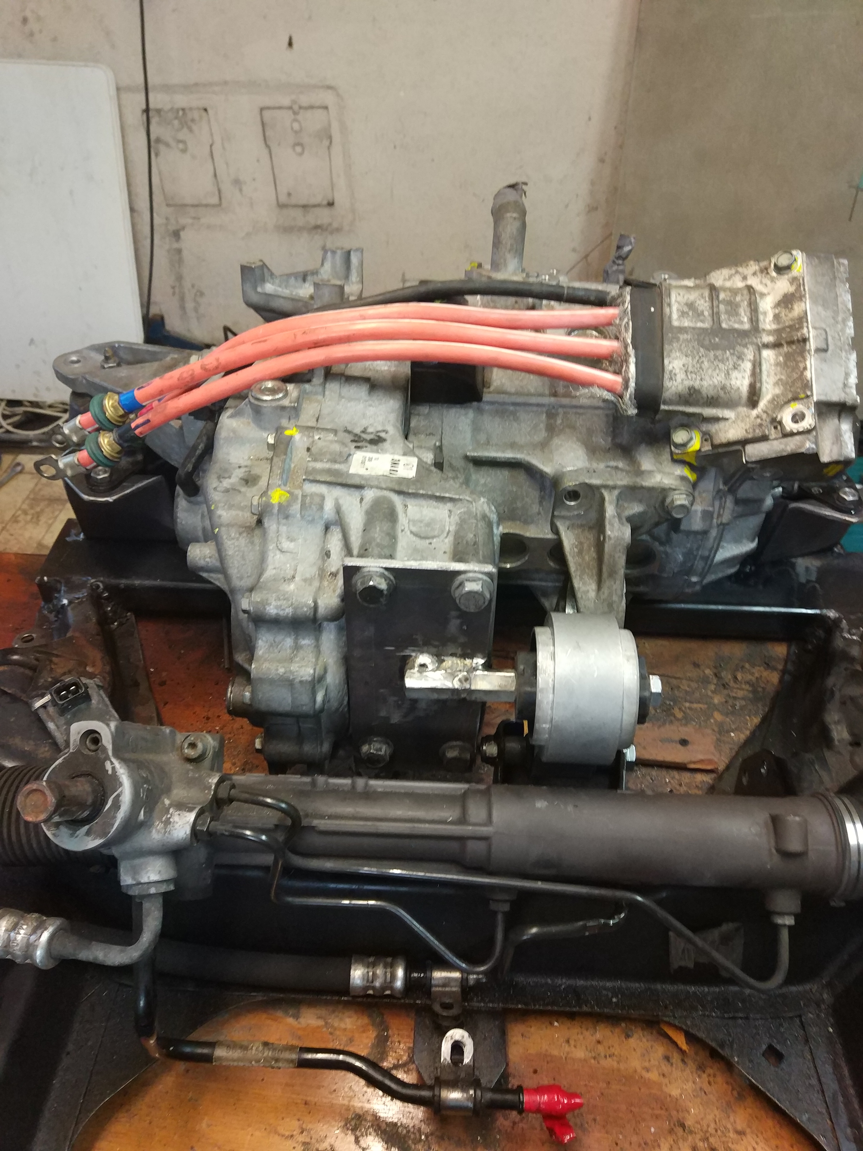
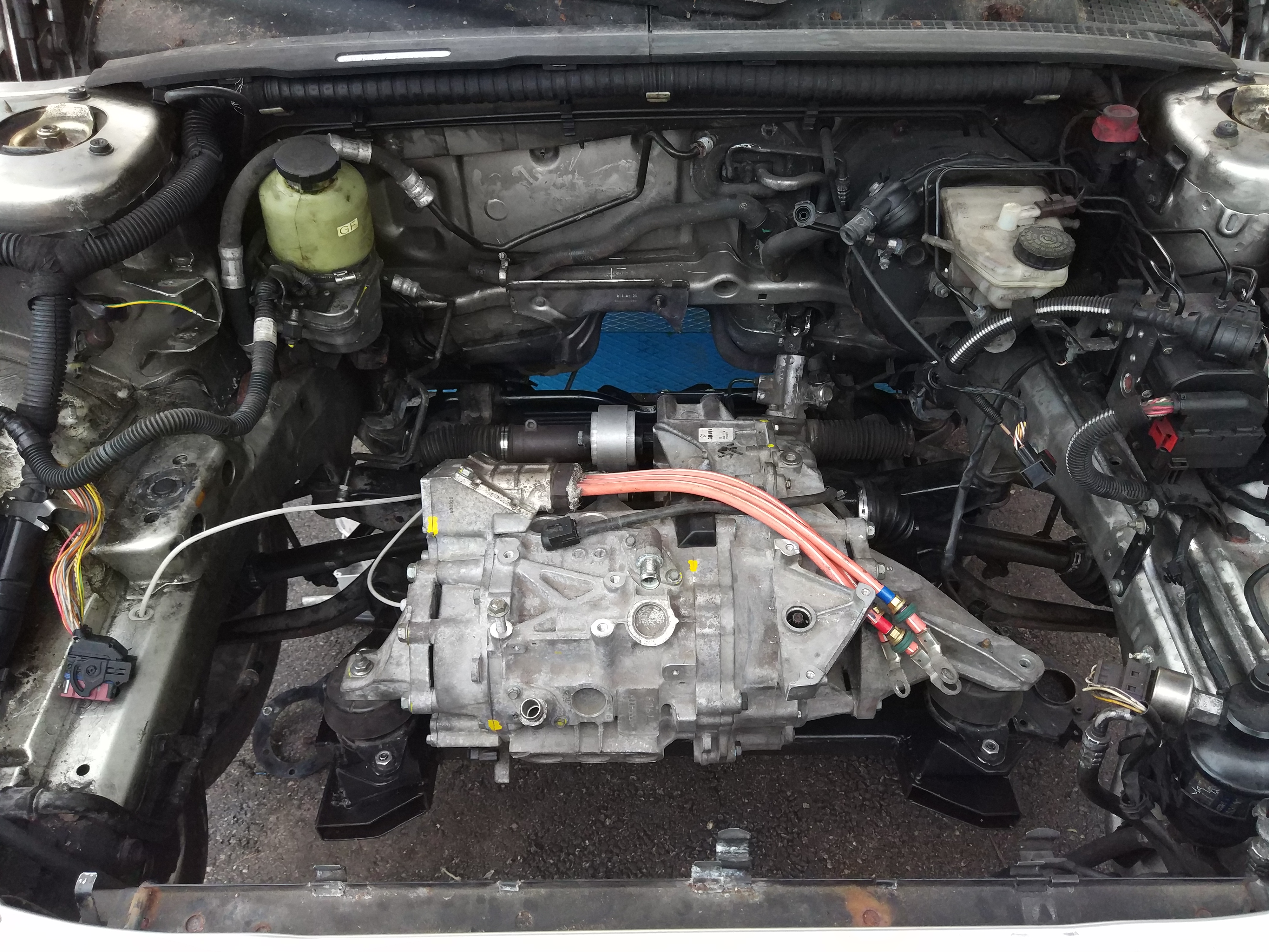
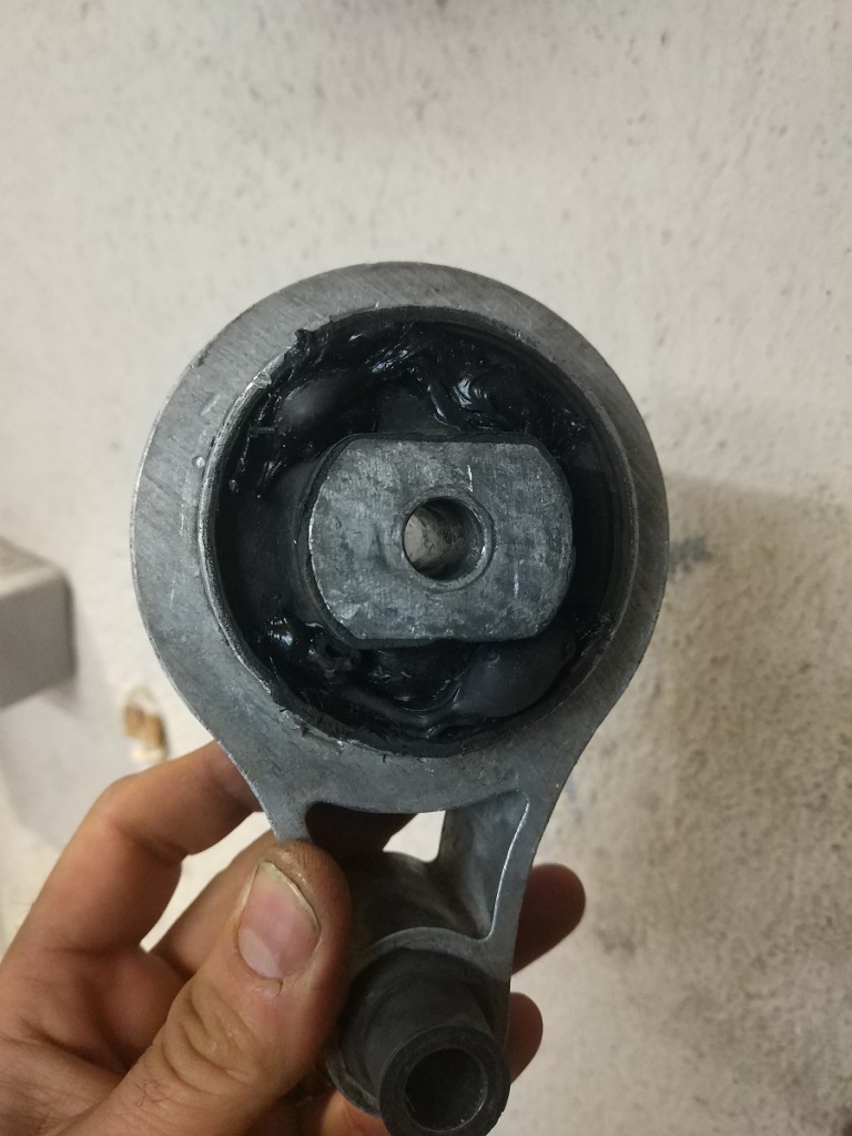
But now i get really good driveoff in reverse. But i still got quite some jolt in the forward direction. That got me thinking my motor mount is to be blamed… It has large holes in its rubber to alleviate vibrations from diesel engine. Electric motor does not oscillate, but rather moves through the whole amplitude. This might move the sealant block center to its edge where it hit the metal edge… bang! Also that move is detrimental to motor position readback.
I took the mount down and filled the holes with some Sika window sealant that is elastic after drying and can withstand a lot of force. After drying off i put the mount back in the car and went for a test run.

That trembling just before stop is gone now. All I had to do is recalibrate sensors.
Vibration has lessened substantially but that mount rubber is still too soft for my liking. I think i will order replacement sealant block and push it in the mount later.

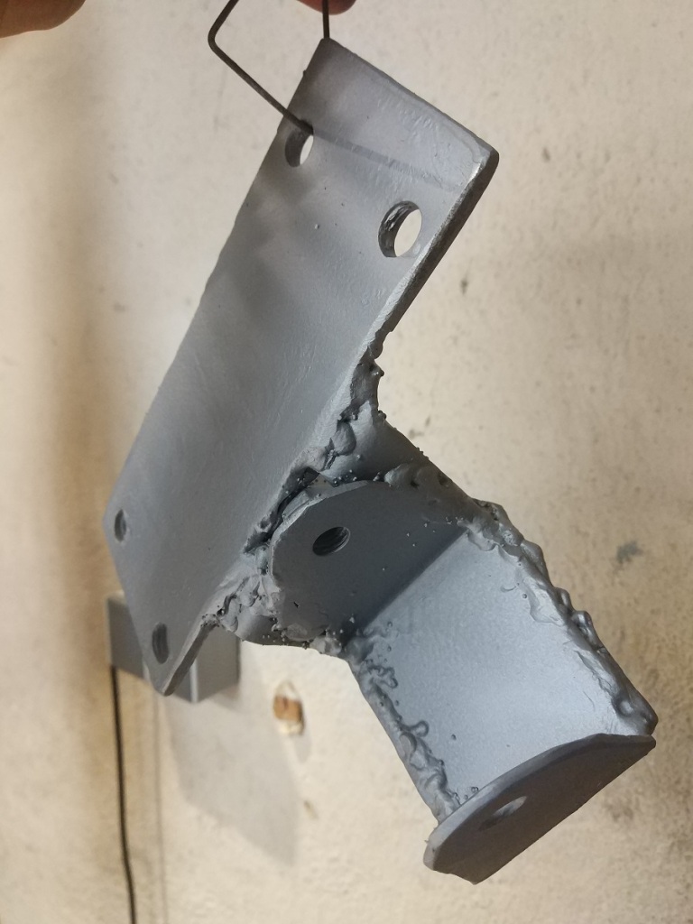
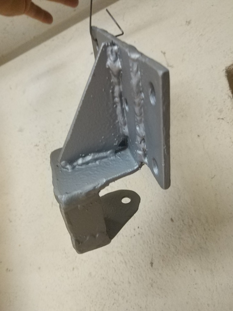
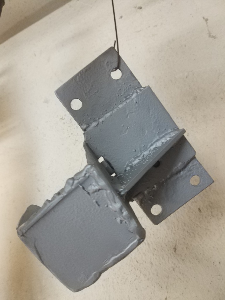
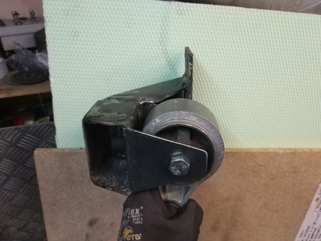
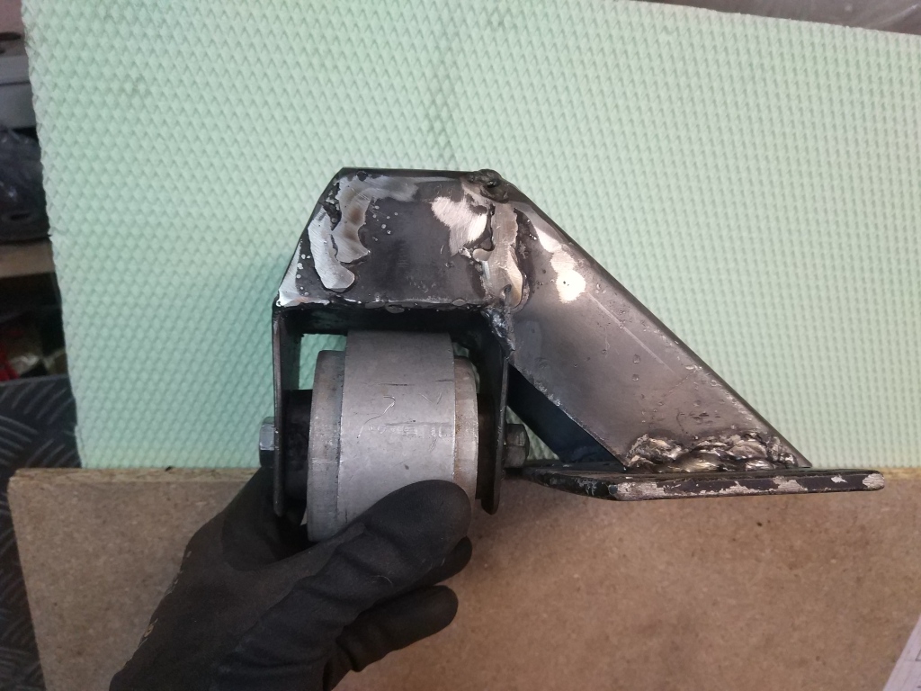
Also i had another problem. All the banging and motor jumping has caused my motor mount to break. It split on the weld seam and was causing terrible noise in my engine bay. I guess 3mm box and my welding skills were not enough to prevent that.
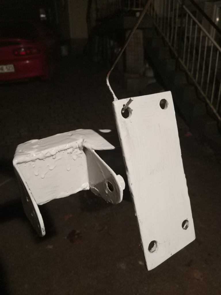
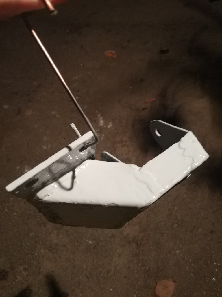
I took One 5mm and cut myself L shape with a brace. It even looks better and more compact now. I welded old fork and new mount together and paint it with Zinc spray.
I finally gave it a coat of black paint and then put it in the car. Now there is no more banging and motor feels really firm.

Busted rear mount

My negligence caught up with me. If you remember from the motor mounting post i made a rather flimsy rear mount and convinced myself that torque will only pass through it in one direction. Well DOH! Torque passes through it from two sides…sometimes more than one reversals in a second! This really stressed the 12mm bolt which was fixed only from one side. And last weekend it broke just as i was trying to setup the motor parameters.

Of course motor was jumping at less than ideal settings and caused additional stress in the single mounting point. This sheared the bolt clean off.

I went back to the drawing board and this time i decided to make a propper fork mount with a box fixture. I welded the box on my first try and it seemed it would work.

But i noticed the rear edge of the box leans over to the HPAS body! That is unacceptable and prone to damage. So i decided to cut the box from the plate and reweld it at an angle, so that rear box part would clear the HPAS body behind the motor. There will be a lot of welding involved still!!!

I did a little remodelling on the rear side of the mount. I reduced its height and put in a bit of taper. I also canted the whole assembly upwards so that it will clear the HPAS casing by a good 15mm. I brushed it with epoxy paint to protect it. This paint is really hard when it sets, so i dont mind those brush drops. Later on i will also spray it black as is the whole undercarriage.

Front battery box

I measured space under the hood and made a model of front box cross section to give me a feel how high the box will sit under the hood.

I found out i have like 4cm of space above the engine space, since the hood is curved upwards a bit. So i decided to designed a box in full height 28cm. That will allow me to install the Volt batteries standing. This will take less space up front.

But in the end i had to account for the front curves. I must be able to replace the light bulb and service the connectors there. So i decided to take an edge off from the right side of the box. Material will be 3mm aluminum.

New Doc 2019-07-01 20.28.29

While i am getting the box made i designed the fittings and frame to install the box.

The simplest method would be to simply weld an inverted U channel into motor space. I decided against this since then this would restrict access to component dissassembly in case i should need to take something out.

What i decided on is the right angle fitting welded on to car frame with a bit of console on both sides.

Console will accept U channel frame fastened by M8 bolts and that will carry the weight of the front battery.

On to the U channel and under the box i will adapt a straight brace to carry the weight and keep the box in correct (slightly canted forward) position.

The box will be fastened to the brace by M6 bolts with countersunk heads so the box will have a smooth surface inside.

The front fittings will carry another U channel, but box will lie on it directly. I welded that with my new MIG inverter welder with flux wire. I consider the process rather easy. The device is easy to setup. 0.8mm wire is elegant and good for most sheet metal. The only real problem is flux emits a lot of smoke that shields the arc. This remains on the weld as ash that has to be cleaned off after. On the pictures you can see the difference before and after cleaning. Otherwise the welds are strong and good looking.


I got battery box home.

IMG_20190711_211244

The 60mm x 60mm dent in the right side will allow me to still get access to right light to change the headlight bulb.

EDIT: I figured i will have to modify the dent some more. I will make it 60mm x 120mm so there would be more space around the box.

I made both braces from U channel slightly larger than welded fittings. This will brace the box and i use them to accept bolts from the box. I made a lot of holes for M6 countersunk bolts. This allows me to still keep relatively smooth box floor. Also i used another bent sheet to support the box at correct height. This allowed me to have the fittings welded easier, much lower and with more support on carrying member. I bolted all holes together and welded the nuts on the underside so i only have to access bolts from the upper side. This greatly helps with dissassembly.


The shock brace however seems that will be very close fit. I am thinking of cutting the box down some 15mm so there will be enough space to fit the box under the brace.

I also tried to fit the inverter along the box. I made a very heavy square fitting which i dont like since it eats the space for contact box.

I decided to make a 5mm alu sheet spacer which will reinforce the left battery box wall so i would be able to mount inverter directly to it. It fits rather snugly.

In the end i fastened all the bolts and enjoyed the smooth surface. I got a helper to test the box.

IMG_20190727_184136

Next i tried fit some finished Kokam batteries from my Mazda to see if they will fit. I may just transplant the batteries to keep the range as before. They fit nicely with spare space for 2mm isolating rubber matt. I would be able to fit 10x of mazda bundles of 8cells. That is like 80% of mazda cells in front box only!

Before i assemble everything for good i decided to paint all added metal parts with epoxy primer paint. This should last for another 10 years :).

Jože made me a cover for battery box out of 1.2mm stainless steel sheet. It looks really good.

IMG_20191005_210042

Subframe is in

I managed to put the subframe in the Pug. I am amazed how much space is left around it. I will use this space and remount the HPAS pump in the left of the pic. I tshould go somewhere in front.

IMG_20190521_200711

Also i plant to mount AC compressor directly to the motor. Pipes are right there. I will only have to make the interface with compressor.

Vacuum pump will go right there under the brake cylinder. That way all brake components will be easily accessible.

I am a bit worried by high shaft angle. The way motor is suspended now those shafts are loaded and i can feel some resistance if i try to move the wheels by hand. I hope this will change when i load the batteries under hood.