I spend some time on a Pug wiring today. I wanted to find the speedo sensor and RPM sensor. Speedo uses a spindle and a magnet to sense rotation. RPM sensor just reads holes in steel ring.


I tried to simulate speedo to determine what is the ratio of the signal. To my surprise i found out speedo senses 1:1 signal. That means 1000rpm shows as 115km/h very close to the drive shafts RPM. I simulated this by using a cordless drill on two settings.
First was 1000rpm and it showed 115km/h speed.
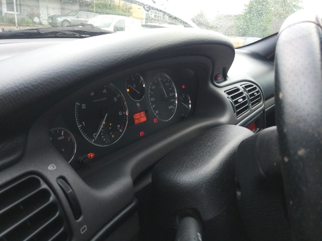
Second was 300rpm and it showed 35km/h speed.
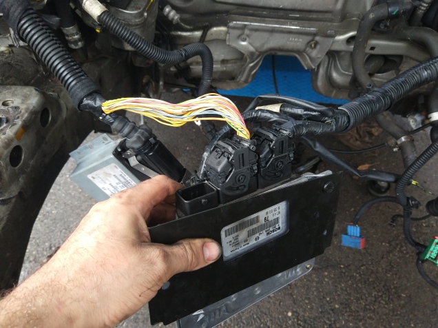
Then i tried to disconnect Engine computer and transmission computer to determine if they are needed. I could disconnect the wires at will and the system only showed
- transmission fault, of course it is not there, i will have to disable the lights
- immobilizer fault, yes i had the ECU/BSM disconnected. Thiss will go off
- Coolant fluid low, no engine no fluid. This will be rectified
- Brake fluid error, brakes are disconnected. I will connect them
- Fuel level low, well i took the tank off. I will use this to show SOC.
- 12V Battery low or not charging, i took the alternator off. I will connect DCDC soon
There are also two other dials. Right one is for engine coolant temperature and the left one is for engine oil temperature. I will use the coolant temp gage to show my engine temp. The oil temperature i will try to replace with my Watt/Volt/Amps/SOC display.
I could test the speedo and odometer to work by my cordless drill, but RPM indicator is a magnetic sensor. I will need something ferrous in the drill jaws. So i made a quick test case…


This wheel will allow me to briefly test if cars BSM reacts just to the RPM sensor. The way i see it, it should solve the problem with:
- Immobiliser
- RPM indicator
- Internal devices like seat heating and cabin fan will start to work
- Car will not go into ECO mode anymore 🙂
After multiple tries i wasnt able to get the RPM needle to jump.
I tried to mechanically excite sensor.
I tried to input RPM using signal generator.
RPM sensor is passive reluctance type with two wires. No. 1 green wire is sensor + and no. 2 white wire is sensor -. I cut the wires off, spliced them for greater length and routed them inside contact box where i can have access even after car will be converted.

Hi Arber
Are you going to use the existing gearbox in the car or a leaf one ??
Thanks in advance.
Stephen
LikeLike
I have a Leaf gearbox and i modified its driveshafts to fit Pugs wheels. Now I use Lebowski brain board that works the motor up to 10000rpm.
LikeLike