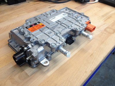
Last week i decided to buy another DCDC to test with higher than 400Vdc. I decided on Chevy Volt Gen2 DCDC P/N 24284603. It is a small and compact liquid cooled unit.
As i am not the first to try to get it to work it is fitting to explain this unit does not work with CAN bus. It accepts a PWM signal which gives it correct key to start and provide desired voltage and constant current.
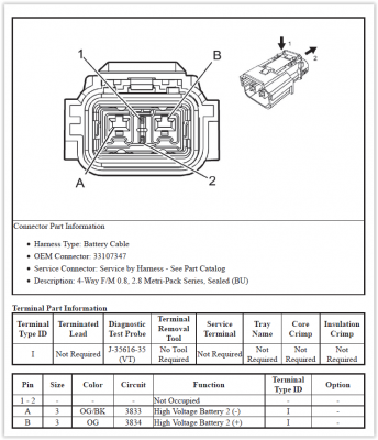
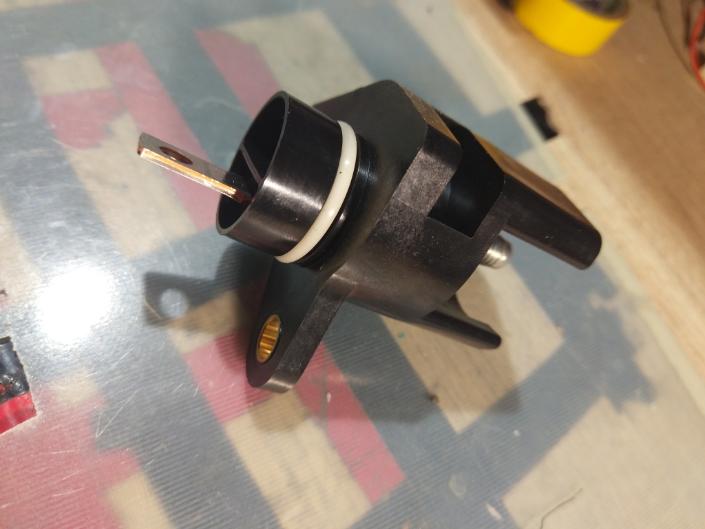
I ordered HV connector from Mouser Aptiv P/N 33107347
I also got pins P/N 15446674
Only connector is not enough. You need to get the end cap P/N 13824779 with rubber seal P/N 15513451. Seal is not easy to get. I imagine i could use silicon glue to seal the cable in. As it was i had some HV connectors left from Ampera/Volt Gen1 and looks like endcap with seal is compatible.
Also i got LV connector JST P/N ATSSPB-C0805H-1AK
I also got pins P/N SAIT-A03T-M064
Both connectors are available in single quantity and they fit and lock good!
When i tried to provide good PWM signal there was something wrong. I couldnt get DCDC to start. I tried various PWM signals and duty.
I tried to start DCDC and when i connected 360Vdc i got 70% PWM on pin 3. This is signal HV is connected, but LV is not started. So far is good. Then i applied 12V 100Hz 75% PWM to pin 1 and …nothing!
No change in pin 3 and no 14V source. I tried 75% from 100Hz to 1000kHz… I figured pin 1 has some pulldown and when i gave it 12V via transistor i got 5V on the pin.
I had 12V battery connected. I connected 370Vdc to main connector. Then i verify LV connector pin3 is at 70% PWM. Then i use my signal generator and connect it to IRF510 Mosfet and i use 330R pullup to signal 75% PWM on Pin1. Nothing…!
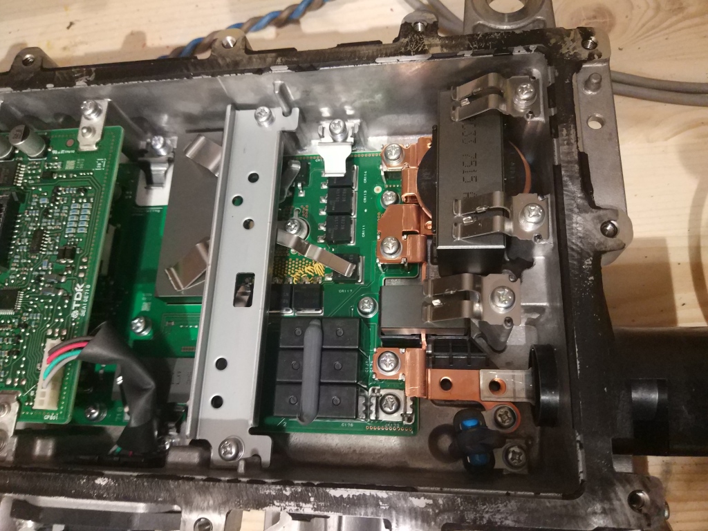
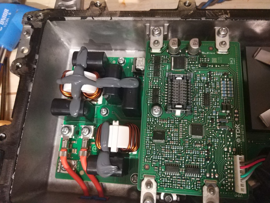
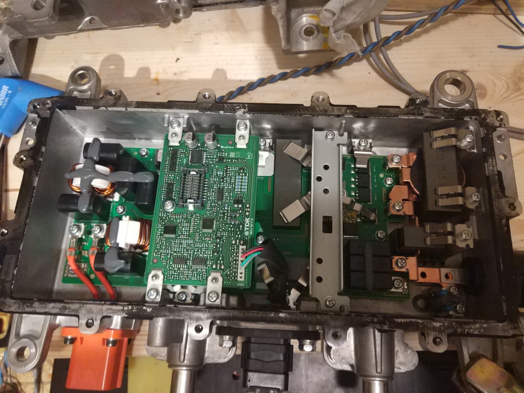
Next i went and took apart DCDC. I found a small control board and connector where PWM signal enters the board. If i traced the signal route everything checks out. There had to be something else!
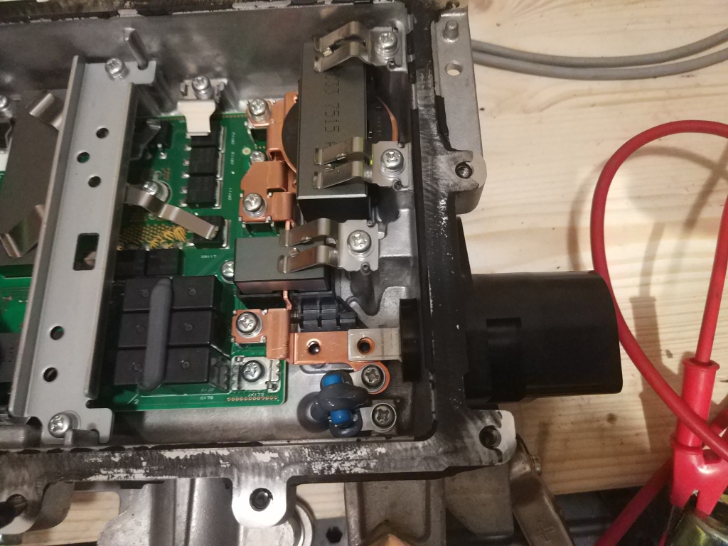
I went by the 12V power route and immediately i found out that directly behind the main power stud there was no 13V and it was immediately behind the plastic separator. And i thought it was separator. Probably it is a fused link and in my case it burned out!
Now that i went on and connected 12V battery directly to output link behind the casing and feed 110Hz 50% duty PWM DCDC came alive. DCDC works with 110Hz up to 140Hz PWM.
Also i noticed that if i would remove the signal at that point DCDC would keep providing power regardless the signal. Later i would reduce duty to 40% and device would shutoff. The funny thing is if i would then remove this 40% duty signal DCDC would come online and provide power at 13.6V as failsafe.
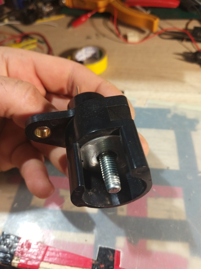
That M8 plug that looks like a fuse has a base plate that is actually connected to internal contact but M8 stud itself is NOT! Since i did not connect this directly to the plate my contact was weak or no contact at all. Of course DCDC sensed there was no 12V battery connected and it wouldnt work.
Then i tried to provide various PWM duty at 110Hz. Those values are under light load with 12V battery attached.
70% ……..14.2V
77% ……..14V
63% ……..13.8V
40% …….. OFF.
I also found out signal works down to 45% duty where DCDC actually stops. It will be interesting to setup my DUE for 70% PWM output on ENABLE signal and 30% PWM when signal is not present to keep DCDC off when car is off too.
I connected my 1kW load of 9 H4 light bulbs directly to the output. I could measure 14V at 74A = 1kW! Supposedly it should provide 2.4kW power when liquid cooled.
EDIT: I tried to run DCDC with 104S battery at 407Vdc and it worked. DCDC comfortably made 14.2Vdc under 1kW load.
